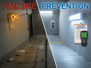
The Perfect Inspection Playbook: 500+ Consecutive Passes
Track record: 500+ installations, 2,200+ inspections, zero failures
This isn’t luck. It’s systematic design and documentation that anticipates inspector requirements before they ask.
The system: Standardized documentation package + modular design approach that adapts to any facility while maintaining proven compliance elements.
—
✓ The 5-Document Package Inspectors Expect
Inspectors aren’t just verifying code compliance—they’re confirming systems will work during actual fires. Documentation proves this better than physical inspection alone.
—
Document #1: Design Basis Report
Purpose: Explains reasoning behind every design decision
What it must contain:
□ Facility description and occupancy classification
□ Hazard analysis identifying fire risks
□ Applicable codes and standards (NFPA editions, local amendments)
□ Design criteria and performance objectives
□ System type selection justification
□ Water supply analysis and calculations
□ Design limitations and assumptions
Why inspectors demand it:
Shows engineer understood specific facility risks rather than applying generic solutions. Provides context for inspector review—they see why you did what you did.
48Fire standard: 8-15 page report completed during initial engineering phase, reviewed with inspector during plan review stage
Example that works:
> “Machining Area 2 contains CNC equipment using petroleum-based cutting oils creating Class II combustible liquid hazard per NFPA 30. Standard ordinary hazard protection (0.20 gpm/sf) is inadequate for rapid fire spread potential from pressurized oil spray. Design specifies 0.30 gpm/sf density with fast-response heads (135°F activation) providing response within 90 seconds versus 3-4 minutes for standard configuration.”
Inspectors reading this understand design intent immediately—no questions about higher-than-typical density.
—
Document #2: Hydraulic Calculation Package
Purpose: Proves system can actually deliver required water flow
What it must contain:
□ Water supply test results (date, location, static/residual pressure, flow rate)
□ System demand calculations for most remote area
□ Pipe sizing calculations showing adequate flow capacity
□ Pressure calculations at every node in system
□ Margin analysis showing design uses ≤90% of available supply
Why inspectors scrutinize it:
Hydraulic adequacy determines whether system actually works. Undersized pipes or inadequate supply create systems that fail during fires despite passing physical inspection.
48Fire quality standards:
✓ Professional engineer seals all calculations
✓ Calculations printed and bound (not just digital files)
✓ Key assumptions highlighted and justified
✓ Alternative scenarios analyzed
Inspector verification checklist:
□ Starting pressure matches water supply test results
□ Flow rates at each head meet minimum requirements
□ Pipe sizes handle calculated flows with acceptable friction loss
□ Most remote area properly identified
□ Pressure at most remote head exceeds minimum threshold
□ Design uses ≤90% of available supply
Common rejections 48Fire avoids:
✗ Outdated water supply test data (over 1 year old)
✗ Unrealistic pressure assumptions
✗ Incorrect pipe friction coefficients
✗ Arithmetic errors in manual calculations
✗ Missing engineer’s seal or unlicensed preparer
—
Document #3: Equipment Specifications and Approvals
Purpose: Verifies approved equipment installed correctly
What it must contain:
□ Manufacturer specifications for all major components
□ UL/FM approval listings for devices
□ Compatibility statements (heads, pipe, valves from compatible systems)
□ Submittal data sheets with inspector approval stamps
□ Material certifications (pipe, fittings, welding materials)
Why inspectors require it:
Ensures listed/approved equipment installed per manufacturer requirements. Prevents mixing incompatible components. Verifies equipment suitable for specific application.
48Fire process:
1. Assemble complete submittal package before installation starts
2. Inspector reviews and approves during permit process
3. Install equipment matching approved submittals exactly
4. Maintain submittal-approved equipment inventory
Critical rule: Product substitutions require re-submittal and approval. Installing different manufacturer’s heads than submitted—even if “equivalent”—fails inspection.
—
Document #4: As-Built Drawings
Purpose: Shows what was actually installed (not what was planned)
What it must contain:
□ Actual installed piping layout (not design intent)
□ Measured dimensions from permanent building features
□ Sprinkler head locations and types
□ Control valve locations with operating instructions
□ Fire department connection locations
□ Detection device locations and zones
□ Tamper switch and flow switch locations
Why inspectors demand it:
Design drawings show plans. As-built drawings show reality. These differ in 90% of projects due to field conditions requiring modifications.
48Fire documentation process:
During installation: Field personnel mark up design drawings noting all deviations
After completion: CAD technicians create final as-builts within 2 weeks
At final inspection: As-builts provided immediately (not weeks later)
Inspection failure scenario (competitor approach):
Inspector finds sprinkler heads in different locations than design drawings show.
Contractor: “Field modifications for ductwork conflicts.”
Inspector: “Did you recalculate hydraulics for modified layout?”
Contractor: “Layout changes were minor.”
Inspector: FAILED—prove modified layout meets hydraulic requirements.
48Fire avoids this: Document all field modifications, recalculate hydraulics when required, provide accurate as-builts showing actual installation.
—
Document #5: Test Reports
Purpose: Proves system actually functions
What it must contain:
□ Hydrostatic pressure test results (pressure, duration, leaks found)
□ Flow test results (measured flow, pressure, duration)
□ Alarm test results (every device tested, signal verification)
□ Integration test results (coordinated systems operation)
□ Deficiency lists (problems found and corrected)
□ Final acceptance test report (system operational verification)
Why inspectors verify testing:
Physical inspection can’t prove system works—only testing demonstrates functionality. Test reports provide evidence system meets performance requirements.
48Fire testing standards:
✓ Witnessed testing whenever possible (inspector present during critical tests)
✓ Comprehensive reports with photos of test equipment setups
✓ All deficiencies documented with corrective actions and retest results
Complete test report format:
□ Date, time, personnel present
□ Equipment used (calibrated test gauges)
□ Test procedures followed (NFPA standards referenced)
□ Measured results (actual numbers, not just “pass”)
□ Acceptance criteria (what results needed to achieve)
□ Pass/fail determination with justification
□ Required corrections (if any deficiencies found)
□ Retest results (demonstrating corrections effective)
—
✓ The 3 Design Elements That Always Pass
Element #1: Conservative Margins Throughout
The approach: Design systems with cushion beyond code minimums
| System Element | Code Minimum | 48Fire Standard | Reason |
|---|---|---|---|
| Water supply | 90% of available | 75-85% of available | Margin for pressure fluctuations |
| Head spacing | Maximum per code | 80-90% of maximum | Coverage margin for obstructions |
| Pipe sizing | Calculated minimum | Next size larger (borderline cases) | Prevents restrictions from sediment |
| Battery backup | 24 hours | 72-90 hours | Extended power outage protection |
| Clean agent | 100% calculated | 110% calculated | Accounts for enclosure leakage |
Cost impact: Adds 8-12% to baseline material cost
Value: Eliminates borderline designs that technically meet code but fail inspector scrutiny
—
Element #2: Accessible and Labeled Components
The principle: If inspectors (or maintenance staff) can’t reach it, you designed it wrong
Control valves:
□ Located 4-6 feet height
□ Clearly visible
□ 36-inch clearance
□ Large signage: “FIRE PROTECTION SYSTEM CONTROL VALVE—KEEP OPEN”
Fire department connections:
□ Visible from street
□ Clearly labeled
□ No obstructions within 10 feet
□ Signage indicates system type and pressure requirements
Alarm devices:
□ Mounted per manufacturer specifications
□ Clear labeling
□ Pull stations have “FIRE ALARM—PULL DOWN” instructions
Detection devices:
□ Labeled with zone identification and device address
□ Smoke detectors show manufacturing date (10-year replacement tracking)
Test connections:
□ Accessible without tools or ladders
□ Labeled with flow rate requirements and drainage instructions
Inspector perspective: Accessible, labeled components demonstrate system designed for long-term maintainability—not just initial installation.
—
Element #3: Integration Documentation
The requirement: Systems coordinating with other building systems need documented integration testing
Critical integration points:
Fire alarm → HVAC shutdown
□ Document sequence testing showing air handlers shut down upon alarm activation
Fire alarm → Access control
□ Document door unlock sequence testing during alarm conditions
Sprinkler flow → Fire alarm
□ Document signal transmission from flow switches to alarm panel
Fire alarm → Mass notification
□ Document message activation and intelligibility testing
Fire pump → Generator
□ Document automatic transfer testing and pump startup verification
48Fire integration reports include:
□ Sequence of operations description
□ Test procedures and acceptance criteria
□ Test results with timestamp logs showing actual sequence timing
□ Photos or videos of tested sequences
□ Confirmation all systems operate as designed under actual conditions
Inspector verification: Activate one system, observe others respond correctly. Documentation shows this testing already occurred—inspector verification becomes confirmation rather than discovery.
[Talk to an Expert!](/contact-us)
—
✓ The Pre-Inspection Process (2 Weeks Before)
Week -2: Documentation review
□ Review all documentation for completeness
□ Verify test reports include all required elements
□ Confirm as-built drawings reflect actual installation
□ Check equipment against approved submittals
□ Walk entire system verifying physical installation matches documentation
□ Photograph any questionable areas with explanatory notes
□ Prepare deficiency list for items requiring correction
48Fire quality control: Internal inspection by senior engineer not involved in installation. Fresh eyes catch problems installation team missed.
Week -1: Deficiency correction
□ Complete all identified corrections
□ Retest any modified components
□ Update documentation reflecting corrections
□ Conduct final walkthrough
Result: Inspector sees completed, verified system—not work in progress requiring return visits.
—
✓ Day-of-Inspection Protocol
Inspector Arrival Checklist
□ Provide complete documentation package (bound, organized, indexed)
□ Brief overview of system highlighting unique features or design considerations
□ Site walk following inspector’s preferred sequence
□ Immediate access to all spaces (no waiting for keys or occupants)
□ Test equipment available if inspector wants verification testing
□ Knowledgeable personnel available answering technical questions
48Fire’s day-of team:
✓ Project manager present
✓ Installing contractor present
✓ Engineer available by phone for technical questions
✓ All documentation pre-reviewed by inspector during permit process
Inspector satisfaction factors:
□ Documentation completeness—no missing reports or calculations
□ Professional presentation—bound, organized, easy to review
□ Responsive personnel—questions answered knowledgeably and immediately
□ System accessibility—easy to inspect without delays
□ Quality installation—workmanship meets professional standards
—
✓ Common Inspection Points (What Inspectors Always Check)
Water Supply Systems
□ Fire department connection accessible, labeled, correct thread type
□ Supply piping size matches calculations
□ Control valves accessible with position indication
□ Backflow preventers (if required) installed and tested
Sprinkler Heads
□ Correct type and temperature rating for location
□ Proper orientation (upright/pendent)
□ Adequate clearance (18 inches minimum)
□ No painting or damage
□ Proper spacing per approved plans
Pipe and Hangers
□ Adequate support spacing per NFPA 13 tables
□ Proper hanger types for pipe sizes
□ Correct pipe materials and joining methods
□ Proper pitch in dry pipe systems
□ No dead-end pipes without drains
Valves and Trim
□ OS&Y valves in fully open position
□ Tamper switches installed on all control valves
□ Valve identification signs
□ Drain and test connections accessible
□ Check valves installed correctly preventing backflow
Fire Alarm System
□ Panel powered with battery backup tested
□ All devices wired and supervised
□ Correct device types for locations
□ Proper spacing per NFPA 72
□ Audible devices meet sound level requirements
□ Visual devices meet candela requirements
System Integration
□ Flow switches wired to fire alarm panel
□ Tamper switches supervised and alarming
□ HVAC shutdown functional
□ Door controls operational
□ Mass notification working
48Fire advantage: Standardized design approach ensures all elements present and correct on every installation—no surprises.
—
✓ Special System Inspection Checklists
Dry Pipe Systems (Inspector Concerns)
What they look for:
□ Proper pipe pitch for drainage
□ Auxiliary drains at low points
□ Quick-opening device sizing
□ Air compressor capacity
□ Nitrogen use versus compressed air
48Fire documentation addressing concerns:
□ Slope verification measurements throughout system
□ Auxiliary drain location diagram
□ Quick-opening device calculation justification
□ Compressor specification meeting NFPA requirements
□ Nitrogen system specification (preferred over air)
Physical verification:
□ Inspector can see proper pitch
□ Auxiliary drains accessible and visible
□ Quick-opening device properly sized and installed
□ Compressor running and maintaining pressure
—
Pre-Action Systems (Inspector Concerns)
What they look for:
□ Interlock logic correctness
□ Detection system integration
□ Manual release functionality
□ Air pressure supervision
□ Proper device selection
48Fire documentation addressing concerns:
□ Logic diagram showing interlock sequences
□ Detection system specifications and testing
□ Manual release testing with witnessed activation
□ Supervisory signal verification
□ Device selection justification (cross-zoned, etc.)
Physical verification:
□ Controlled activation test demonstrates proper interlock operation
□ Detection system properly installed and wired
□ Manual release accessible and labeled
—
Clean Agent Systems (Inspector Concerns)
What they look for:
□ Enclosure integrity
□ Agent concentration calculations
□ Discharge nozzle placement
□ Pre-discharge warning systems
□ Egress time adequacy
48Fire documentation addressing concerns:
□ Enclosure integrity test results (door fan test)
□ Agent calculation sheets sealed by engineer
□ Nozzle placement diagram showing even distribution
□ Pre-discharge alarm testing with timing verification
□ Egress analysis showing adequate evacuation time
Physical verification:
□ Enclosure closures functional
□ Nozzles properly positioned
□ Pre-discharge warnings audible throughout space
□ Manual abort accessible
—
✓ When Inspectors Find Issues (Response Protocol)
Even perfect systems occasionally face inspector questions. Here’s the protocol:
Step 1: Listen Carefully
□ Don’t interrupt or argue
□ Understand inspector’s perspective
□ Identify specifically what concerns them
Step 2: Reference Documentation
□ Show design basis addressing the concern
□ Present calculations or test results
□ Explain justification for design approach
Result: Most questions resolve when inspector sees documentation.
Step 3: Acknowledge Valid Concerns
□ If inspector identifies actual deficiency, acknowledge immediately
□ Explain how it will be corrected
□ Provide timeline for correction
Step 4: Request Clarification
□ If code interpretation differs, request specific code section
□ Discuss interpretation professionally
□ Document discussion and resolution
Step 5: Correct Promptly
□ Minor corrections: Complete during inspection
□ Major corrections: Schedule with confirmed return inspection date
□ Document all corrections with photos
Step 6: Update Documentation
□ Photograph corrections
□ Update as-builts if physical changes made
□ Revise reports if calculation errors found
—
✓ The Performance Scorecard
48Fire Inspection Results
Total installations: 500+
Total inspections: 2,200+
Failed final inspections: 0
Minor corrections required: 2-3% of inspections
- Labeling adjustments
- Small component adjustments
- Documentation clarification
Major corrections required: 0%
- No design changes
- No equipment replacement
- No substantial rework
Industry Average Comparison
Inspections requiring corrections: 15-25%
Major corrections requiring re-inspection: 3-5%
48Fire advantage: 90-95% better first-pass rate
—
✓ The ROI Calculator
Direct Cost Savings Per Project
| Cost Item | Without 48Fire Approach | With 48Fire Approach | Savings |
|---|---|---|---|
| Reinspection fees | $200-$500 | $0 | $200-$500 |
| Correction labor | $1,500-$8,000 | $0-$300 | $1,500-$7,700 |
| Schedule delays | 2-4 weeks | 0 | Time to market |
| GC supervision | $2,000-$5,000/week | $0 | $4,000-$20,000 |
| Total typical savings | – | – | $4,000-$14,000 |
Indirect Benefits
Contractor reputation: Building owners prefer contractors passing first inspection
Reduced project risk: No unknowns delaying occupancy
Insurance recognition: Documented quality improves premium negotiations
Reduced liability: Thorough inspection approval demonstrates code compliance
Long-term value: Systems passing rigorous initial inspection typically have fewer maintenance issues. Proper documentation enables efficient maintenance and future modifications.
—
✓ Your Pre-Inspection Checklist
Use this checklist to prepare for your next fire protection system inspection:
Documentation Package (Complete?)
□ Design basis report (8-15 pages)
□ Hydraulic calculations (sealed by PE)
□ Equipment specifications and approvals
□ As-built drawings (reflecting actual installation)
□ Test reports (hydrostatic, flow, alarm, integration)
Design Elements (Verified?)
□ Conservative margins (75-85% water supply, not 90%)
□ Accessible components (4-6 feet height, 36-inch clearance)
□ Clear labeling (all valves, devices, connections)
□ Integration testing (documented with timestamp logs)
Physical Installation (Ready?)
□ All equipment matches approved submittals
□ No field substitutions without re-approval
□ Control valves in open position
□ Tamper switches installed and functioning
□ No painted sprinkler heads
□ Proper clearances maintained
□ All connections tight and secure
Personnel (Available?)
□ Project manager on-site
□ Installing contractor on-site
□ Engineer available by phone
□ All personnel familiar with system details
Final Verification (Completed?)
□ Internal inspection by independent engineer
□ All deficiencies corrected
□ Documentation updated
□ Test equipment available if inspector requests verification
—
Why This Playbook Works
500+ consecutive passed inspections prove the system:
Anticipates requirements: Documentation prepared before inspector asks
Eliminates surprises: Internal verification catches problems early
Demonstrates quality: Professional presentation shows attention to detail
Provides confidence: Comprehensive testing proves functionality
Ensures consistency: Standardized approach applied to every project
48Fire doesn’t just meet inspection requirements—we exceed them. The result: Zero failed inspections across 500+ installations saving clients $4,000-$14,000 per project while delivering systems inspectors trust and building owners rely on.
Ready to pass your next inspection on the first try?
[Talk to an Expert!](/contact-us)
—